Chapter 1: Setup and Basics
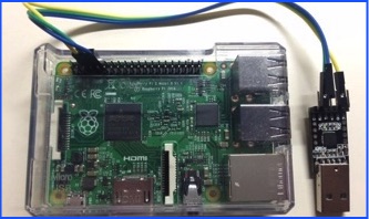
This is the JayStation2. I designed the CPU and GPU, and etched all the transistors with my own two hands. Except that I didn’t. This is the excellent Raspberry Pi 2 B+. Also shown: James Lee’s serial to USB cable he loaned me so I could do some proper kernel reloading/debugging.
Disclaimer: I do not work for Sony. Despite the disturbing percentage of my shirts, jackets, and bookbags that are PlayStation dev-related, I have never worked for Sony. I do, however, have many friends that work at Sony, some of which I hope will call off the corporate lawyers. JayStation is in no way associated with Sony or PlayStation, and any stupid things I say represent only my own ineptitude and silliness.
Hardware Setup
Assume you have prepared all the necessary materials: a Raspberry Pi 2B+, MicroSD card, MicroSD writer, a serial to USB cable, and a micro USB cable like the one the Orbis DualShock 4 uses. Everything I talk about should work both on Mac and PC, and when there are differences I will try to mention them.
Hardware setup is fairly simple. The MicroSD card goes in the SD card slot, the small end of the micro USB cable goes in the Raspberry Pi, and the other end goes in a USB port to power the system. The serial to USB setup is a bit more complicated. I am currently borrowing a coworkers cable that he purchased from pluggable.com. Both Mac and PC drivers are available at http://plugable.com/drivers/prolific
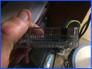
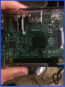
Connect the cable to the RPI2 GPIO pins and the USB connector as shown in the following three pictures.
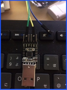
Not shown in the above image is the blue wire being connected to the TX pin of the USB connector. Remember the labeling of the pins on the USB connector are from the host’s perspective, not target. TX means from host to RPI, and RX means from RPI to host.
Host Software Setup
We’re going to compile and load a kernel image, but the Raspberry Pi needs more to boot. Unlike most systems, on the Pi the GPU is king. It starts up first and bootstraps the CPU. If you want to read more about the process, I found this quite useful: https://thekandyancode.wordpress.com/2013/09/21/how-the-raspberry-pi-boots-up/
Long story short, there are lots of necessary files. Luckily Linux has taken care of that for us. Go to https://www.raspberrypi.org/help/noobs-setup/ and follow the easy guide to installing a Linux distro on your SD card. Once that is done, mount your card and you will see two kernels: kernel.img and kernel7.img, the difference being RPI1 will try to boot from kernel.img and RPI2 will use kernel7.img. Booting your own OS only involves replacing the kernel7.img on your card with whatever you build.
To actually compile (assemble) your source files, you will need a compiler and assembler. I recommend installing the excellent Yagarto package, located at http://sourceforge.net/projects/yagarto/. I use it at home on Mac and at work on Win7, so setup is the same on both machines. Make sure its added to your path at the end so that make can find it.
All that’s left is creating the directory structure, makefile, linker script, and writing some source. My directory tree looks something like this
root
|-------- kernel.ld
|-------- makefile
|-------- source
|-------- main.s
|-------- project
|-------- slickedit.vpj
|-------- sublime2.sublime-project
|-------- xcode.xcodeproj
The slickedit and xcode projects are makefile projects that map build menu items to makefile targets, but you can skip that if you just want to call make manually. You don’t even need to use an IDE if you don’t want.
The kernel.ld linker script is interesting if you’ve never seen this kind of thing before. The simplest script I use looks like this:
SECTIONS
{
.ivt 0x0000 :
{
*(.ivt)
}
.init 0x8000 :
{
*(.init)
}
.text :
{
*(.text)
}
.data :
{
*(.data)
}
/DISCARD/ :
{
*(*)
}
}
You are basically naming sections and optionally specifying what address they get loaded at. For example, by default the hardware wants the interrupt vector table loaded at address zero, so you’d create a section called .ivt and specify that it be loaded at address zero. In the actual source, you want to tell the linker what goes where by adding .section .ivt right before your interrupt vector table, but we’ll cover that in depth at another time. Also worth noting is the .init section at 0x8000. There is nothing magical about this number, its just what Linux seems to use by default and you can change it. You will place your startup code in this section, and then set the stack to 0x8000. Code will start at 0x8000 and go up, while the stack will grow down towards lower addresses. The above linker script will get you through the first few chapters, but you’ll need something else when we start initializing different stacks and using the MMU to do memory protection and virtual memory.
Thats it. Now just make all to build your kernel, and copy the kernel7.img file to your SD card.
Miscellaneous Information
For the first few chapters of this story, your new best friend is going to be http://www.cl.cam.ac.uk/projects/raspberrypi/tutorials/os/downloads/SoC-Peripherals.pdf
While this guide is for the BCM2835 used in the RPI1 and not the BCM2836 used in RPI2, with a little modification most of the information still applies. Especially worth noting is the information on addresses. The addresses listed in the peripherals manual are bus addresses, and all begin at 0x7E000000. To translate that into the physical addresses, just replace that 7E with 3F. So if the manual tells you the base address of the ARM timer registers is 0x7E00B000, you will use 0x3F00B000. Incidentally the RPI1 peripherals started at 0x20000000, so if you see some RPI1 site telling you the UART registers base address is 0x20201000, then you will use 0x3F201000.
There are a few other differences as well. For example, some of the GPIO pins have changed, notably for the light. Also, some things that previously wanted to be pulled low now want to be driven high. Those are some of the main gotchas when going from RPI1 to RPI2