Chapter 2: There Is A Light That Never Goes On
This is Morrissey. He is not a developer and has nothing to do with this blog aside from I happen to be listening to The Smiths as I wrote this.
Disclaimer: I do not work for Sony. Despite the disturbing percentage of my shirts, jackets, and bookbags that are PlayStation dev-related, I have never worked for Sony. I do, however, have many friends that work at Sony, some of which I hope will call off the corporate lawyers. JayStation is in no way associated with Sony or PlayStation, and any stupid things I say represent only my own ineptitude and silliness.
Usually I’m no fan of poetry, but even I must admit I sometimes enjoy the work of Steven Patrick Morrissey who once remarked on the difference between RPI1 and RPI2
Take me out tonight
Where there’s registers and GPIO pins I can write
Driving the pins high
I never ever want to pull low
Because thats RPI1
Thats RPI1
Turning on an LED is the hello world of embedded programming. Except its better. Unlike hello world where there is usually a million things standing between you and the hardware, this is more immediate. It feels more real. You are directly making it happen rather than calling some mystery function in some mystery standard library calling some mystery system calls in a mystery OS that does who-knows-how-much work to make your text appear on screen. It also happens to be a great way to initially debug things on a system with no debugger (yet) and no way of knowing where and why the CPU died running your code. So with that purpose in mind, lets go.
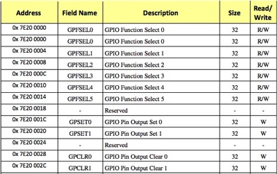
There are two steps needed to turn on the light. We want to set the function for pin 47 and then drive it high. Thats it. The registers we’re going to use to set the function are memory mapped to the GPIO base address (0x3F200000) and up. They have three bits per pin, meaning each 32 bit word can control 10 pins. That is to say 10 pins * 3 bits per pin = 30 bits. To further overexplain
0x3F200000 : pins 0 - 9
0x3F200004 : pins 10 - 19
0x3F200008 : pins 20 - 29
0x3F20000C : pins 30 - 39
0x3F200010 : pins 40 - 49
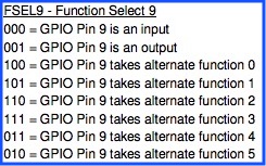
So if we want to set something for pin 47, then 0x3F200010 seems to be the place. That register starts with pin 40, we want 47, and each pin is 3 bits, so the bits we care about are 21, 22, and 23. So lets go ahead and set it to 0b001, meaning output.
.equ GPIO_BASE_ADDR, 0x3F200000
.globl js2osTurnOnActLED
js2osTurnOnActLED:
// loads the physical address of the GPIO region into r0.
ldr r0,=GPIO_BASE_ADDR
// we want pin 47. Every word contains 3 bits per pin * 10 pins.
// so pin 47 is 4 words (16 bytes) in, and is pin 7 * 3 = 21
mov r1,#1
lsl r1,#21
str r1,[r0,#16]
Ignore the fact that I am zeroing out all the other GPIO pins for the moment. Now all we need to do is drive the pin high. Interestingly, there are two different registers for driving a pin high and pulling it low. Its not just a matter of writing a one or zero to the same place. To drive the pin high and turn on the light, write to GPIO base address + 32. To pull it low, all we'd have to do is write the same value to GPIO base address + 44.
mov r1, #1
lsl r1, #15
// Drive GPIO 47 to high, causing the LED to turn on.
str r1,[r0, #32]
...
mov r1,#1
lsl r1,#15
// Pull GPIO 47 to low, causing the LED to turn off
str r1,[r0,#44]
Great, you have a light on now, but how can we use that to debug? For example, we can flash it a different number of times depending on where we get. If you make it past point A, flash once. If you make it past point B, flash twice. If some value is greater than the expected max, flash it three times. Its not perfect but it is a start.
To make the timer flash, I’m going to use one of the many interesting timers. This one happens to be a doubleword that counts microseconds and requires no special setup. To access it, just read two consecutive words from its base address
.globl js2osGetTimestamp
js2osGetTimestamp:
// timer address
ldr r0, =0x3f003000
// load two word timer
ldrd r0, r1, [r0, #4]
mov pc, lr
That gets the timestamp. For a quick initial pass at making your timer, just read the current time, add on the number of microseconds you want to wait, and then spin polling the timer until its above the expected time. Now you should have everything you need to get the lights blinking for asserts and debugging